|
|
|
|
Treatment |
|
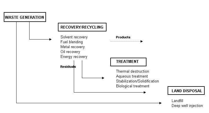 Recovery/recycling facilities recover material as a salable product. Treatment facilities change the physic al or chemical characteristics of the waste, or degrade or destroy waste constituents, using any of a wide variety of physical, chemical, thermal, or biological methods. Land disposal facilities are permanent repositories for the disposal of waste materials. There are some differences between a commercial, off-site facility and a captive, on-site facility. The off-site facility accepts waste from outside its own community, while an on-site facility handles only that waste generated by what could be a long-standing and important economic activity in the community. From the technical perspective, the off-site facility generally handles a wider range of waste types and is typically larger and more complex. Ignoring this, however, the risks posed by off-site and on-site facilities are comparable, and depend far more upon types of waste received, design, operation, and other site-specific factors. The two types of facilities must meet the same hazardous waste regulations. Design Requirements Operations design at the hazardous waste facility should be guided by the following five subsystems: Pre-shipment analysis; Waste receiving; Waste Storage and preparation; Container processing; Waste treatment; and Residuals management. A typical layout for a hazardous waste facility is shown at the end of the chapter. It is important to keep in mind that all the above components operate under the umbrella of a number of special measures. These special precautionary measures include: Security; Inspections; Maintenance; Training; Incident Prevention; Emergency Planning; Safety; Monitoring; and Auditing. Pre-Shipment Waste Analysis A waste analysis plan is a critical part of the facility. The plan should be specified the parameters for which each waste should be analyzed, the sampling and analytical procedures to be used, and the frequency of analysis. Before the facility treats, stores, or disposes of a waste, it must profile the waste. This is also called full characterization of the waste, by the generator, prior to shipment. Representative sampling of a waste shipment is conducted upon arrival at the facility to verify that the composition of the shipped waste matches the fully characterized waste. The purpose of the full characterization before shipment is to satisfy the following requirements: Determination if the waste is acceptable for receipt at the facility in terms of the capability of the facility to treat or dispose of the waste; Identification of inherent hazards of the waste so that appropriate precautions can be taken during its handling and storage at the facility to prevent incidents; Determination of physical characteristics and chemical constituents of the waste to allow selection of effective waste processing and disposal methods; Selection of verification parameters to be tested upon arrival at the facility. These parameters will ensure that each shipment of waste is the same as the fully characterized waste; Selection of any treatability parameters to be tested which could vary so as to influence how waste processing would be programmed; and Development of a cost estimate for treatment and disposal. Waste Receiving Waste shipments typically arrive by truck at the facilitys gatehouse. Upon accepting the waste, the facility should sign the manifest and send a copy to the generator. At that point, the facility will share liability with the generator and the transporter. Thus, it is critical that pre-shipment waste analysis has already been completed and the shipment scheduled. Without prior scheduling of the incoming shipment or if the shipment is improperly documented, the gatehouse will have to refuse entry to the truck. Scheduled and properly documented shipments are directed to the receiving station where any packaging is checked, the loaded truck is weighed, and representative samples are collected for testing the verification parameters. The waste may arrive as bulk liquids in a tank truck, containerized liquids or sludge in drums, bulk shipments of contaminated soil in dump trucks, or by a number of other methods. Collecting a representative sample can pose a difficult task considering that a waste may be in multiple phases and states, or have pockets of high concentrations. The receiving station should use previously established procedures for each situation to ensure the collection of a representative sample. Upon collection of a sample, the laboratory should analyze a portion for the verification parameters and should retain the remainder for subsequent testing of treatability parameters. Upon verification of the waste shipment, the truck should be directed to an unloading area, where it should be emptied and then reweighed before it leaves the facility. The mere emptying of a truck can pose a difficult challenge if the waste has stratified, a container has leaked, or a solidification reaction has occurred. It is important to have plan procedures and have prepared special equipment to resolve such problems. Furthermore, the truck may need to be decontaminated to remove any trace residues. Waste Storage and Preparation After unloading, the wastes should be moved into storage that can consist of tanks or impoundments for bulk liquids, hoppers for solids and sludge, or pads and warehouses for containers. The objectives of storage and preparation are fourfold: Store waste safely before introduction as feed into the system of unit treatment and disposal processes; Provide adequate accumulation time during periods when treatment and disposal processes systems are out of service; Facilitate mixing, blending, and repackaging of waste as deemed necessary; and Allow staged input of various wastes with regard to the subsequent unit treatment processes. An obvious important safety consideration is fire prevention and protection. The storage of certain types of hazardous waste requires automatic alarms and possibly sprinklers. The facility must provide adequate water supply for extinguishing fires plus the capability to collect and store fire waste runoff. The storage and treatment of any water-reactive waste necessitates an alternative type of fire protection system. A key issue in providing safe storage is compatibility. This has two independent considerations: The compatibility of the waste with the material used to construct the container, tank, or liner in contact with the waste; and The compatibility of the waste with other waste stored together. Container Processing Wastes could be delivered to the Hazardous Waste Treatment Facility in various sizes and types of container. The wastes should then be extracted form the containers and the containers will be processed and cleaned. Clean, competent containers could be sold back into the market for reuse. Clean, punctured or defective containers should be crushed and transported to the Sorting and Recycling Facility. Waste Treatment While waste is maintained in storage, a treatment schedule is developed that will identify the waste to be treated, its storage location, any necessary preparations, the method of treatment, and the rate at which the waste is fed. Upon commencement of waste treatment operations, the waste is typically fed by bulk materials handling systems such as pipelines or conveyors to the equipment used to perform the prescribed treatment steps. Treatment operations may be carried out on a batch or continuous basis. The facility should monitor operations carefully to assure that the performance attains the desired results. Operational monitoring should be done with instrumentation, direct human observation, and chemical analysis. This typically involves extensive record keeping using a combination of computers, chart recorders, and manually entered paper logs. Hazardous waste should be treated using any of a large number of commercially proven unit processes. The treatment methods fall into the following four categories: Phase separation (sedimentation, steam stripping, etc.); Component separation (ion exchange, electrodialysis, etc.); Chemical transformation (chemical oxidation, incineration, etc.); and Biological transformation (fixed film aerobic treatment, etc.). The selected method of treatment not only depends upon the type of waste, but on the wastes individual physical and chemical characteristics and the specifications for the treated waste. The unit treatment processes can be interconnected to attain more efficient and more effective treatment. Residuals Management Each waste treatment process produces gaseous emissions, wastewater effluents, or residuals requiring subsequent management, if not additional treatment. An incinerator, for example, produces combustion gases that require scrubbing, that in turn produce an acidic wash-water requiring wastewater treatment. Incineration may also produce fly ash and bottom ash requiring disposal, if not treatment. The unit treatment processes are not the only operations that generate residuals. Spillage and runoff from storage areas may also require treatment. The opening of containers may need to be done under negative atmospheric pressure with the fumes collected and treated. A full-service facility can usually provide all necessary treatment of residuals. Smaller facilities may have to collect the residuals and transport them as hazardous waste to another facility capable of treating them. Special Measures A Waste Treatment Center should take a number of special precautionary measures for all of its day-to-day operations to prevent incidents. These measures can be listed as follows: Security; Daily Inspection; Emergency planning; Continuous Employee training; Safety; Monitoring; and Strict Auditing procedures. Conceptual Design As part of the conceptual design, the designer should take into consideration the waste characterization studies to propose the most adequate processes to be included at the treatment facility. Based on input from the local authorities, incineration and solidification facilities are usually included at the treatment facility. Steam stripping, Carbon Adsorption, and Chemical Oxidation may also be included as part of the physico-chemical methods. Attached-growth, Aerobic Batch Reactor, Conventional liquid phase treatments will also be considered as part of the biological methods included in the Hazardous Waste Treatment Center. A brief discussion on these methodologies is provided below. Steam Stripping This process is utilized for the removal of volatile and sometimes semi-volatile compounds from wastewaters. The process is capable of reducing volatile organic compounds (VOCs) in water to very low concentrations. Steam strippers are based on the transfer of organics from the liquid phase to the gas phase. Higher concentrations of organics in a steam stripper require complex process design techniques. A schematic diagram of a steam stripper operating at atmospheric pressure is presented below. The bottom portion of the steam stripper is stripping wastewater in a manner similar to an air stripper. This is known as the stripping section of the column. The top section of the column, above the feed point, is known as the rectifying section. This section of the column enriches the organics content of the steam to a point where a separate organic phase can be achieved in the overhead decanter. The steam is enriched because it is (theoretically) in equilibrium with the saturated liquid that is fed to the top of the column. |
|
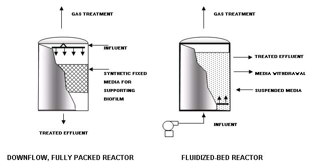
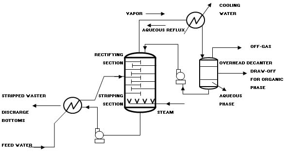 The combination of the stripping and rectifying section is a mass transfer process known as distillation in the chemical process industry. The contaminated water feed to the steam stripper is preheated to near-boiling temperature by exchanging heat with the stripped water exiting from the bottom of the stripping column. The contaminated water enters the column at the feed point, and the water flows downward through the stripping section of the column. Steam passes counter-currently up through the column. The column operates at a temperature that is slightly higher than the normal boiling point of water, usually in the range of 215 to 220 oF. The temperature difference between the top and the bottom of the column is modest, generally on the order of a few degrees Fahrenheit. At the elevated temperatures inside the column, the volatile organics in the water exert a higher vapor pressure than at ambient conditions. As the organics vaporize in the column, they are transferred from the liquid phase into the gas phase. As the stream travels up the column, the concentration of organics increases in the striping steam. The steam exits the top of the column where it undergoes a phase change to a liquid in the overhead condenser. This liquid is supersaturated with the organics so a separate organic layer forms in the decanter. The aqueous phase from the decanter is returned to the top of the column where it flows down the column. This aqueous phase is saturated with the organics because the organic concentration in the aqueous phase is in equilibrium with the separate organic phase in the decanter. An analysis of phase-equilibria thermodynamics and a mass balance will show that, because this fed to the top of the column is saturated with the organics, the steam leaving the top of the column will contain a high enough concentration of organics to form a separate organic phase when the steam is condensed to a liquid phase. Carbon Adsorption In the Carbon Adsorption process, a soluble contaminant (the adsorbate) is removed from water by contact with a solid surface (the adsorbent). The adsorbent most widely used in environmental applications is carbon that has been processed to significantly increase the internal surface area (activated carbon). Use of different raw materials and processing techniques results in a range of carbon types with different adsorption characteristics. Activated carbon is available in both powdered and granular form. Granular activated carbon (GAC) will be used for removal of a wide range of toxic organic compounds from ground water and industrial waste streams. Powdered activated carbon is often used in biological treatment systems. Typical activated carbon contactors are cylindrical tanks where carbon is held in place by a plenum plate. Contaminated water enters the top of the cylinder or column, it makes contact with the carbon and exits through a drain system at the bottom. The system will be accompanied by air scouring and back washing facilities to avoid head loss due to accumulation of solid particles present in the influent. Furthermore, the system will allow removal of spent carbon for regeneration, and the addition of new carbon. The system will comprise a continuous flow of columns, set up in series so that the final column in the system is in effect a polishing unit. Because the downflow beds also act as filtration units, they will be periodically backwashed. Chemical Oxidation The objective of having chemical oxidation treatment at the facility is to be able to detoxify waste by adding oxidizing agents to chemically transform waste components. Chemical oxidation of wastes is a well-established technology that is capable of destroying a wide range of organic molecules, including chlorinated VOCs, mercaptans, phenols, and inorganics such as cyanide. This section focuses on the oxidizing agents most commonly used for hazardous waste treatment: Ozone; Hydrogen peroxide; Chlorine; and Ultraviolet light (UV). Oxidation and reduction reactions occur in pair to comprise an overall redox reaction. In chemical oxidation for hazardous waste treatment, an oxidizing agent is added to oxidize the waste components of concern, which serve as the reducing agents. Oxidizing agents are nonspecific and will react with any reducing agents present in the waste stream. Therefore, these processes are most economical when organics other than the ones of concern are in low concentration. Although chemical oxidation is typically applied to liquid hazardous wastes and contaminated ground water, soils may also be amenable to these processes. Contaminated soils can be excavated and treated in a slurry form in reaction vessels. However, because excavation is an expensive process, the tendency in soil cleanup technology is to use in situ processes. Chemical oxidation will be conducted in completely mixed tanks or plug flow reactors. The contaminated water is introduced at one side of the tank and the treated water exits at the other side. The oxidizing agent is either injected into the contaminated water just before it enters the tank or is dosed directly into the tank. Complete mixing, which prevents short-circuiting in the tank, is necessary to ensure contact of the contaminants with the agent for a minimum period of time, and, thus, reduce the chemical dosage required to obtain a specific effluent concentration. Ozone is produced from atmospheric oxygen using electrical energy to split the oxygen into two oxygen radicals, which readily combine with other oxygen molecules to form ozone. Ozone is unstable under normal environmental conditions and readily decomposes back to oxygen. Ozone is added to the liquid waste as a gas, either through porous diffusers at the bottom of a tank, of through an injector where the pressure drop produced draws ozone into the injector and mixes it with the liquid. Attached-Growth Systems These systems rely on the ability of the microorganisms to attach to surfaces of inert media. Contaminated water will be passed through a bioreactor housing the media. The resulting microbial growth attaches to the media and forms a thick film. The biomass remains in the reactor except that which sloughs off the supporting media. Part of the effluent and biomass may be recycled. These systems can develop high concentrations of biomass in relatively small reactors because relatively little biomass is lost with the effluent. This results in a low food to microorganism ratio and the long solids retention time necessary to foster slow-growing microorganisms. Both enhance degradation of hazardous contaminants, particularly waste with low concentrations of organics. Attached-growth systems require that the microbes have the ability to attach to the appropriate media; such ability varies among strains of microbes and will be examined during the definitive design phase. The field of municipal sewage treatment historically has relied extensively on trickling filters, a form of attached-growth treatment using rock as the inert media. Fluidized bed reactors may be utilized. The fluidized bed is achieved by growing the biofilm not on a fixed media but on particles of sand or other inert media. The influent is introduced from below the bed in an upflow reactor; the upflow velocity must be sufficiently high to keep the particles suspended. Withdrawal of treated effluent from the top of the reactor maintains the upflow velocity. A portion of the inert media is withdrawn periodically as the bed expands. These systems can remove more organic loading per unit reactor volume than other fixed-film processes. Two examples of modern attached-growth systems are shown below. |
|
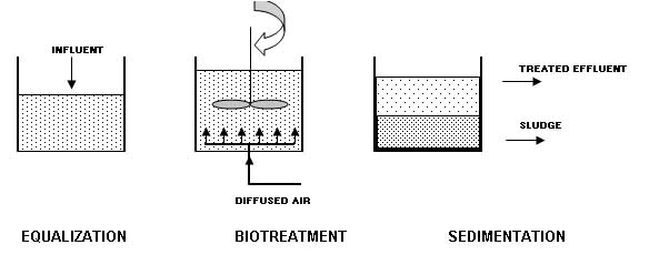
 Aerobic Batch Reactor Systems Batch reactors may be utilized due to their proven capability to foster genetic exchange in the microbial community of a bioreactor. Batch reactors combine equalization, bio-treatment, and sedimentation in a single tank. The systems are called sequencing batch reactor (SBR) because they conduct the equalization, bio-treatment, and sedimentation sequentially. The figure below shows an aerobic batch reactor system. The biomass will be maintained by discharging only the clarified effluent after the sedimentation step. The time allocated to each step will be adjusted within the constraint of the incoming flow. This provides much greater flexibility than continuous flow systems, allowing SBRs to achieve high performance when treating variable wastewater. The simplicity and the flexibility of the SBR approach makes it especially appropriate for small-scale processes. |
|
 If the flow to be treated is continuous, at least two SBRs will be needed. Placing the SBRs in series helps ensure that the biomass in each tank is acclimated to the transformed compounds being discharged from the previous tank. Conventional Treatment Conventional liquid-phase treatment consists of technologies, or variants, originally developed for treatment of industrial wastewater. The typical hazardous wastes treated by this method include contaminated ground water and industrial process wastewater containing toxic organic substances. This method will consist of passing aqueous hazardous waste through a reactor containing either suspended or attached biomass of highly active and acclimated microorganisms. The flow can be continuous or batch, and the reactor can be operated under aerobic or anaerobic conditions. Oxygen is added in aerobic systems by diffused aeration. The liquid waste receives treatment both before and after biological treatment. Pretreatment consist of several steps dependent upon the types of waste to be treated: Equalization to dampen/modulate hydraulic surges and variable organic loading in continuous flow systems; Chemical treatment to precipitate toxic metals, if present, but could involve other steps such as breaking of emulsions; Physical removal by sedimentation of metallic precipitates, removal of floating material and others; and Conditioning to supply nutrients and to adjust pH to optimum range. After pretreatment, the liquid waste will flow into the bioreactor where the dissolved organics are metabolized by the biomass with a resulting growth of cellular mass. This can be achieved only by biodegradation. The actual yield of biomass depends on numerous factors. Not all utilization of substrate results in synthesis of cells; some substrate is oxidized to produce energy. Additional treatment will be required after the reactor by adsorption, ion exchange, or microfiltration methods. The removal of a portion of organic waste occurs by methods other than biological. Volatilization can result in significant removal of some organics, especially in aerated systems. Some organics may not be metabolized but absorbed with colloidal contaminants onto the biomass. In sum, abiotic losses can account for significant amount of the organic waste removed with no reduction of the toxic nature of the waste. The chemical constituents have merely been transferred to other media which may require their own particular treatment. Liquid Injection Incineration When it comes to incineration of hazardous waste, there is more experience with liquid injection (L.I.) incinerators than all other types combined. The greatest proportion of hazardous waste incinerators in operation today are the LI type. The waste in burned directly in a burner (combustor) or injected into the flame zone or combustion zone of the incinerator chamber (furnace) through atomizing nozzles. The heating value of the waste is the primary determining factor for the location of the injection point. Liquid injection incinerators are usually refractory-lined chambers (horizontal or vertical flow, either up or down), generally cylindrical in cross section, and equipped with a primary burner (waste and/or auxiliary fuel fired). Often secondary combustors or injection nozzles are required where low heating value materials such as dilute aqueous-organic waste are to be incinerated. LI incinerators operate at temperature levels ranging between 1,000 oC (1,832 oF) and 1,700 oC (3,092 oF). The residence time for the combustion of products in the incinerator may vary from milliseconds to as much as 2.5 seconds. An atomizing nozzle in the burner or the incinerator is a critical part of the system because it converts the liquid waste into fine droplets. The viscosity of the waste determines whether good atomization of a liquid is possible. Two-fluid atomizers, using compressed air or steam as an atomizing fluid, are capable of atomizing liquid with viscosities up to 70 centistokes (2.7 ft2/hr). The physical, chemical, and thermodynamic properties of the waste must be considered in the basic design of any incinerator system. Any commercial facility receiving hazardous waste requires a complete analytical laboratory on site. Most commercial operators require a sample of the waste before they will provide a treatment cost to the generator. The following information about the waste to be burned in the incinerator is required to design and properly engineer the total system and the auxiliary components. Chemical composition; Heat of combustion; Viscosity; Corrosivity; Reactivity; Potential for polymerization; Ash content; and Ash fusion temperature. The atomizer design in the burner or incinerator usually dictates the pressure requirements of the transport system. Where a hydraulic (pressure type) atomizing nozzle is used, requiring high pressures, a pump design with close clearances between the impeller and the housing is needed. High viscosity materials and liquids containing solids will erode the pump surface causing excessive wear and rapid deterioration of pump pressure resulting in a reduction of flow as well as poor atomization. Waste transport is critical in proper design of any incinerator. Some liquid wastes and sludge must be maintained at above ambient temperatures to permit pumping. When cooled, these wastes will solidify in the pipeline. Conversely, if these wastes are heated too much, they may polymerize. Once polymerized, it may be impossible to re-liquify the material. With heated liquids, pump bearings may become overheated or centrifugal pumps may cavitate, so pump selection is also critical. The method of injection of the liquid into the burner or incinerator furnace is one of the most important features of a well-designed system. The reasons for injecting the liquid as a fine spray are to: Break up the liquid into droplets; Develop the desired pattern for the liquid droplets in the combustion zone with sufficient penetration and kinetic energy; and Control the rate of flow of the liquid discharged to the combustion system. Organic and aqueous liquids pass through three phases before oxidation takes place (Hydrocarbons ignite at temperatures as low as 20oC and as high as 650oC). The liquid droplets are heated, vaporized, and superheated to ignition temperature. These droplets must receive heat by radiation and convection from the furnace as rapidly as is practical. At the same time, they must be in intimate contact with oxygen from the combustion air. If the droplet diameter is large, fewer droplets will be produce per unit flow of waste, and the total surface available for heat transfer is small. In a good atomizer, the droplet size will be small providing greater surface area and resulting in rapid vaporization. It should be taken into consideration that that the burning time for a 300-micron droplet is 150 milliseconds, while only 30 milliseconds are necessary to burn a 125-micron droptlet. There are two basic types of atomizers for liquid wastes. The first is the mechanical or pressure atomizer, which is a small orifice through which high-pressure liquid expands as they go from a high pressure to the low pressure of the combustion chamber. The higher the pressure to the nozzle the better the atomization. Droplet size at full flow is usually on the order of 100 to 150 microns, and atomization deteriorates as the flow is decreased. The mechanical atomizing nozzle is simple in construction, subject to fouling and plugging by small particles, and has poor turndown characteristics. The second type of atomizer is the two fluid internal mix atomizer, where steam or compressed air acts as the second fluid, and the waste or fuel as the first. The two fluids are mixed within the atomizer, and the energy of the steam or compressed air achieves the atomization. Droplets down to 50 microns can result from good internal mix nozzle design. This nozzle still has small orifices so it should not be selected for a dirty liquid waste. It is an excellent atomizer with good turndown. Proper mixing of combustion air with the atomized liquid droplets is very important. As the liquid is vaporized and superheated to ignition temperature, oxygen reacts with the hydrocarbon vapor to produce combustion. As this occurs, there is a sudden rise in temperature increasing the velocity of the gases in the area surrounding the droplets causing greater mixing and completing the reaction. As the viscosity of the liquids increases, droplet size tends to get larger. To completely vaporize and superheat the droplet, more time is needed. Increased turbulence created by high-intensity burners permits this reaction to be achieved rapidly. Greater energy, imparted to the combustion air by fan or blower, provides higher velocities in the combustion zone improving the mixing of the air and the fuel droplets. In many burners this turbulence causes internal recycling of the hot product of combustion providing better heat transfer to the atomized droplets achieving the ignition point more rapidly. If the vaporize liquid contains solids, the incinerator design must allow the particles to be carried into the gas stream without agglomeration. A high swirl or a cyclonic design may cause the solids to be re-agglomerated into larger particles becoming more difficult to burn. Proper design of the air mixing device and the nozzle location are therefore very important. Proper oxygen concentration at the surface of these solids is needed to ensure that gradual oxidation will occur. Because they are solid, the particles will burn at the surface, and heat will be transferred inwardly to the core of the particle. Sufficient time must be provided to permit complete burnout of the solid particles in suspension. It is for this reason that coal is finely pulverized before combustion in a fluid system. Inorganic compounds are carried with the liquid into the gas stream as particulates. Depending on the type of atomizer, the composition of the solid, and the temperature of the primary oxidizer chamber, many particles will be reduced to submicron size and diffused into the gas stream. The heavier particulates may become molten and agglomerate into a molten ash. The combustor must be designed to collect the molten ash without plugging the passages of the incinerator and quench system. A slanted horizontal design or a downward vertical orientation is most often used for these types of waste. Primary and secondary combustion units are utilized in the liquid injection type incinerator systems. Primary units are used to burn wastes having sufficient heating value to burn without the need for auxiliary fuel. With good burner design, heating values from approximately 2,500 kcal/kg (4,500 Btu/lb) and above can be burned without the use of auxiliary fuel. The burner design determines the minimum heating value waste that can be burned without the need for auxiliary fuel. Solidification Solidification is the process of mixing liquid or semi-solid waste materials with pozzolanic materials such as cement kiln dust, lime or flyash. The pozzolanic materials either react directly with the waste materials, taking them up through ionic or covalent bonding, or encapsulate the materials within the structural matrix. Inorganic waste materials are typically bonded to the matrix and may participate in the chemical reactions. Organic chemicals are typically encapsulated within the structural matrix, and do not generally participate in the chemical reactions. Solidification systems are extremely versatile, and can be used to treat virtually all types of liquid hazardous wastes. However, solidification is considered to be most cost-effective for inorganic waste constituents. REFERENCES Freeman, H.M., Standard Handbook for Hazardous Waste Treatment and Disposal, McGraw-Hill, 1999. Shah, K.L., Basic Solid and Hazardous Waste Management Technology, Prentice Hall, 1999. Tchobanoglous, G., Theisen, H., Vigil, A.S., Integrated Solid Waste Management Principles and Management Issues, MacGraw-Hill, 1993. Lagrega, M.D., Buckingham, P.H., Evans, J.C., Hazardous Waste Management, MacGraw-Hill, 2000. |
|
|
|
|
|
|
|
|
Contact us at: enviromed2@yahoo.fr |
|